Thermoplastic vs. Thermosetting Plastic: Key Differences, Properties, and Applications
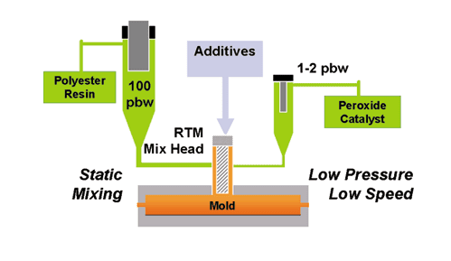
March 30, 2026 Designing a product or part for reaction injection molding (RIM) can be a complex process. Elements such as the materials you plan to use, environmental conditions the part will be subjected to, and your budget will impact choices you make during the design phase.
- Materials have varying specifications for rigidity and finishing options.
- Environmental stressors may necessitate reinforcing materials or other design elements to increase strength.
- Cost can be affected by the material and the complexity of your mold.
We recommend discussing your project with a RIM expert at Osborne Industries to ensure the material you choose meets your specifications. We can also provide customized guidance for your design.
Design Elements
The following best practices serve as general guidelines when designing for RIM. Talk through your project with one of our specialists for tailored advice.
Tolerances and Materials
Tolerances are broader in RIM than with traditional injection molding. RIM can produce large, complex parts with relatively low internal stress, but dimensions may shift because of shrinkage or curing variations. Critical features may require machining or inserts to achieve tight fits.
RIM supports a wide range of thermoset formulations. Parts can be rigid, semi-rigid, elastomeric, or foam-cored. Each material has different features, such as impact resistance, flexibility, or thermal stability, so material should be selected with the end-use environment in mind. Common RIM formulations are based on polyurethane and polydicyclopentadiene (pDCPD) materials.
General guidelines:
- Typical linear shrinkage: 0.004–0.006 inch per inch (0.1–0.15 mm per 25 mm) or 0.4%–0.6%.
- Dimensional tolerance: ±0.010 inch per inch (±0.25 mm per 25 mm).
- Machine or use inserts for features requiring precision fits.
- Select formulations based on application needs (e.g., rigid for housings, elastomeric for impact, foam for lightweight panels).
Wall Thickness
One of the most important aspects of any RIM design is maintaining uniform wall thickness, especially at corners. While some polyurethane designs can support varying wall thickness, consistency will result in more even cooling and reduce material degradation or warping.
Avoid designing walls that are too thick, as this can result in sink (indentions in the part on the finish side that naturally occur during cooling). Your chosen material will impact the allowable depth. You can increase part stiffness without increasing wall thickness by designing walls that are curved, chamfered, stepped, ribbed, or corrugated. Ribs (see below) can add strength and reduce the need for thick walls.
General guidelines:
- Ideal range: 0.125–0.250 inch (3–6 mm) for most RIM parts.
- RIM can handle thicker sections (up to ~1 inch or 25 mm) without sink.
- Uniform wall thickness is ideal for even curing and shrinkage.
- For areas needing extra strength, add ribs to avoid dramatically increasing wall thickness.
Parting Line and Draw Direction
In some designs, the location of the seam where the two sides of your mold meet will be easy to determine. Typically, the top of the part will have a cleaner finish, while the underside will be more complex. But the ideal parting line placement may not be obvious. The same holds true for draw direction when the part is removed from the mold.
Consider the final appearance and how the plastic will cool in the mold when determining where to put your parting line.
General guidelines:
- Parting lines: Place them in the least visible area of the part to reduce the need for additional finishing. Follow the natural geometry of the part by using edges, breaks, or feature transitions to help hide the parting line.
- Draw direction: If possible, design the part with one draw direction, so the part can be ejected with a single straight pull. Align features such as bosses, ribs, and recesses with the main draw direction whenever possible.
Drafting
To ensure the part can be removed from the mold with minimal resistance and no damage, you’ll want to taper or angle certain elements of the design. If possible, avoid 90-degree walls and use angled walls instead.
The deeper the ribs or cavities, the greater the draft required. Keep ribs and cavities as shallow as possible to minimize draft requirements.
More texture in a mold requires more drafting. So, offset any textures with proper angling.
General guidelines:
- Provide a draft of 1–3 degrees on vertical faces to make demolding easier.
- For textured surfaces, increase draft to 3–5 degrees to account for pattern depth.
- Keep the draft direction consistent to avoid complex mold actions.
Ribs
 Ribs are an effective way to add strength, reduce the material required to make a part, and reduce cycle time. They can be a better option than designing thicker walls. Taller, thinner ribs are more effective than shorter, wider ribs, and are less prone to sink. Keep in mind that taller ribs require more drafting, so balance the elements accordingly.
Where possible, place ribs on the non-cosmetic/B-side of the part.
Rib joints at the wall tend to be slightly thicker. Because uniform wall thickness is important, design your ribs with a slight taper at the joint to minimize the impact on the wall depth.
General guidelines:
- Rib thickness should be 50%–70% of the adjacent wall to prevent sink marks.
- Space ribs apart by at least two times the wall thickness to avoid uneven flow.
Cores and Bosses
Cores are mold features that form holes/cavities in the part.
Placement of the parting line and adequate drafting are critical when incorporating cores in your design. For deep cavities, support the part walls around core features with ribs.
Bosses — protrusions often used for fasteners — shouldn’t be isolated. Always support them with gussets or attach them to a side wall.
General guidelines:
- Cores: Maintain at least 0.125-inch (3-mm) wall thickness between the core and the outer surface. For structural parts, keep thickness uniform around cores to minimize warpage.
- Bosses: Wall thickness should be 60%–70% of the surrounding wall. Provide a radius of 0.06–0.125 inch (1.5–3.2 mm) at the base.
Radii and Corners
Using rounded edges in your mold improves resin flow and reduces the chance of air pockets, or voids, forming. Avoid sharp 90-degree angles by using smooth radii.
General guidelines:
- Inside radii should be ≥ 0.06 inch (1.5 mm).
- Outside radii should be slightly larger to maintain uniform wall sections.
Hinges and Clips
RIM materials are not suitable for true living hinges. When designing hinges in RIM, use integrated hinge features such as bosses with through-holes and pin receivers or use metal inserts to create durable pivot points.
Clip fatigue life varies with material and geometry. Some clips may be designed for repeated flexing and must withstand hundreds or even thousands of interactions, while others are intended for single-use applications. In RIM, long-life clips require careful design and material selection to achieve durability.
General guidelines:
- Hinges: Plan for hinge durability testing under real-use conditions, as hinge geometry, cycle frequency, and load can dramatically affect performance in RIM parts. This ensures the chosen design meets functional requirements before production.
- Clips: Add generous radii (≥0.06 inch or 1.5 mm) at the clip root to reduce stress. Use a tapered profile so force is distributed along the clip. Provide a defined flex zone with reduced thickness to control bending.
Inserts and Embedded Hardware
 One of the advantages of RIM is the ability to mold directly over inserts or structural components. Embedding hardware such as threaded fasteners, metal frames, or reinforcing plates can reduce assembly steps and increase part strength. Proper planning is required to ensure good bonding and minimize cosmetic issues.
Inserts should be positioned so the liquid resin flows evenly around them, avoiding shadowed or unfilled areas. Always design smooth transitions between the insert and molded material for better resin flow and reduced stress points.
General guidelines:
- Use inserts for features that require tight tolerances or frequent fastening.
- Plan gating and venting to avoid trapped air near embedded hardware.
- During production, preheat larger inserts to improve bonding and reduce voids.
Surface Finish and Texture
Surfaces range from smooth/polished to coarse/grainy (SPI Surface Finish Classes A to D). The finer the surface, the more expensive and time-consuming production will be. Class A finishes require frequent mold polishing and are typically used only for highly cosmetic parts.
The finish on RIM products closely reflects the mold. While textures can be added after molding, the closer you can get to the final surface within the mold, the less finishing will be required.
General guidelines:
- RIM parts shrink less than injection-molded parts, so textures replicate cleanly.
- Tooling can be textured or polished, depending on the final appearance.
- Large, flat surfaces may show minor waviness. Use subtle curvature or ribs to break them up.
Additional Considerations
- Flow paths that are uniform in your design will reduce knit lines, voids, and uneven curing.
- Gates should be placed in low-visibility areas, as they can appear to be cosmetic defects. Use multiple gates only when necessary.
- Vent properly, ideally at the farthest flow ends, to avoid trapped air bubbles.
- Warpage may result from uneven part cooling, insert positioning, unfavorable geometry, or improper curing.
Ready for a Quote?
If you’re further along in the design phase and would like a quote for your project or review by an Osborne Engineer, fill out our Plastic Molding Project Quote Request form, and one of our knowledgeable representatives will reach out.